
artful enchantment stardewculture project catholic
In the actual projects, there are some documents for this purpose, such as Philosophy of operation, I/O lists, Piping and Instrumentation Diagrams, Internal wiring diagrams and so on. Different types of Siemens PLC programming blocks. How to communicate a PLC system with SCADA via OPC UA? Again, for keeping the logic as simple as possible, I assume that all of the level switches are Normally Open switches and will send a True signal (24-volt DC signal) when they sense the water and they send a False (zero signal) when they do not. In Part 1 of this article, we have explained how to create a new project and configure the PLC hardware. The NC contact of this switch is used in logic, whenever the overhead tank level reaches high limit the limit switch contact opens and gives FALSE value and in normal condition the limit switch contact will remain closed and give TRUE value. It would be nice to share with us your way to create such nice animation. % As explained above when the Auto/Manual switch value is FALSE the contact will be in close state and Manual mode will be selected. /F5 49 0 R 25+ Most asked PLC interview question-answers. Once the level rises high enough, the control switch keeping the tank open is turned off and the water flow ceases. In this scenario if overhead water tank level drops below low level, it will give a high pulse and in turn make the motor coil energized and switch on the motor. endobj
Drinking water distribution monitoring for flow and reservoir/overhead tank level control.  In auto mode both the switches work together to control the level. Thanks in advance. /Type /Page As explained above when the Auto/Manual switch value is TRUE the contact will be in open state and Auto mode will be selected. /F3 43 0 R When the water level reaches low level then pump will be stopped. << In this mode water pump can be started or stopped manually. All Right Reserved. After that, the fill valve remains off until the level drops and the switch is activated, then the process repeats again. There is an ON/OFF mode which does the basic option ON/OFF. We and our partners share information on your use of this website to help improve your experience. Note: The motor will remain in stop position until the overhead tank level drops below low level again. Design parallel tanks level control using plc ladder diagram tutorial. This rung is designed to run this motor in Auto mode with Overhead tank High and Low level switches. As shown in the below image, we have two sensors, Sensor1 will detect whether the water is present in the tank and the Sensor2 will detect the tank is full of water. I close the tag table to start programming. Permissive is a condition or set of conditions which should be satisfied before doing a manual operation. In a connected water system utilizing pumps, motors, and other processes, water is frequently drawn from tanks when its required by other systems. Thank you! Note: Since the start switch is pulse action, we have to push the start switch back to false before we use it again for next time(This is applicable to simulation only). Q: Why do I chose SR Flip Flop over the RS Flip-Flop? /ProcSet [ /PDF /Text ] Technological revolutions hit the industrial world in 1960s, when the development of the rst programmable logic controller (plc) is explored. /MediaBox [0 0 595 842] 4 0 obj
This paper proposes an optimized wireless automatic control technology using a programmable logic controller through. Your email address will not be published. Scenario-5 Motor is in Auto mode, Well water level is more than low level, motor is running and if overhead tank level reaches high level. And assign the address of Q0.0 to that. To implement this logic in PLC programming, lets consider sensor1 as I0.0 and sensor2 as I0.1 inputs and the motor will be as Q0.0 output. Difference between Modular PLC & Compact PLC: To detect high and low levels of overhead tank, two level switches are placed, one at the bottom of overhead tank and other one at the top of the overhead tank, which gives output in digital terms that is when corresponding levels are detected. Thank you for your suggestion. So the motor continues to work until it is switched OFF manually. I have also started youtube channel to learn Industrial Automation technologies like PLC,SCADA, DCS, HMI, IOT, VFD and process Instrumentation. Analog Scaling and Unscaling in PLC Programming. In the next videos, we can continue with the HMI creation. In this scenario if well water level drops below low level, the limit switch will give open contact and give FALSE value to PLC and in turn make the motor coil de-energized and switch off the motor. 2 0 obj
>> Thank you, Canuto! You can also follow us on Facebook and Twitter to receive daily updates. We can simulate various simple applications like this using online PLC simulators. 11. central park postcard book , Tank Level Control Using Plc at Abbie Martel Blog. /Length 10145 >> Again by defining these tags in the tag table, well prevent confusion when were writing the PLC program or during the maintenance and troubleshooting. You can unsubscribe at any time. Most popular 5 different types of plc programming languages. %PDF-1.5
please which web site or link can I use ladder logic diagram for my project reference. Scenario-3 Motor is in Manual mode, motor is running and if Well water level drops below low level. <>
Thats it for this part. The NC contact of the Stop switch is used in logic, when the switch is activated the contact opens and stops the motor from running. Basics of PLC Counter Instructions. /Filter /FlateDecode Different types of PLC Modules. endobj
The next one is the Tank Low-Level Switch with the address of I0.1. 3 0 obj
But in the third case, we have to stop the motor because in this case tank is filled fully with water. Here, we want the fill motor to pump lubricating oil into the tank until the high level sensor turns on. Different types of Siemens PLC programming blocks. How to Size a Cable for Industrial AC Motors? How PLC Counter works? Since we have used pulse input for the start switch, the motor coil output is used to latch the start signal. Thank you sir for this tutorial. The third case represents that the tank is filled fully with water. This is a PLC program to control water level in an overhead tank and this will be a useful guide for people who are interested in learning PLC Ladder logic programming. Thanks for the input. First of all, we have to know what the logic behind our process is. ||
Thanks. When the low sensor switch turns ON the motor turns ON. 25+ Most asked PLC interview question-answers. Read Real Time Clock value in Siemens PLC. Design parallel tanks level control using plc ladder diagram tutorial. In this scenario if we press the stop switch, the switch contact will open and in turn make the motor de-energized low and switch off the motor. There will be two sensors low-level sensor and high-level sensor. As soon as the Low-Level Switch on the tank does not sense the water, PLC should send a start command to the pump and the pump will start working until the High-Level Switch senses the water. Before writing anything within the OB1 environment, we should add the Inputs and Outputs of the project and their addresses in a Tag Table. Your email address will not be published. SIR, YOUR ARTICLES ARE SUPERB YOU ARE GREAT!!! THANKS A MILLION!! The NC contact of Auto/Manual switch is used for Manual mode. 3048 N Cessna Ave, suite 3, Casa Grande Arizona 85122, United States +1 (520) 585-4595 sales@florightpump.com, Feel Free to Contact us via phone or send us a message on our contact page, Water Tank Level Control Using PLC Programming. This rung is designed to run this motor in Manual mode with Start/Stop switch. To check run time scenarios we have to press the icon shown below and put the online PLC simulator to simulation mode. Note: Motor will remain in stop position until the well water level is more than low level and someone press start switch again.
In auto mode both the switches work together to control the level. Thanks in advance. /Type /Page As explained above when the Auto/Manual switch value is TRUE the contact will be in open state and Auto mode will be selected. /F3 43 0 R When the water level reaches low level then pump will be stopped. << In this mode water pump can be started or stopped manually. All Right Reserved. After that, the fill valve remains off until the level drops and the switch is activated, then the process repeats again. There is an ON/OFF mode which does the basic option ON/OFF. We and our partners share information on your use of this website to help improve your experience. Note: The motor will remain in stop position until the overhead tank level drops below low level again. Design parallel tanks level control using plc ladder diagram tutorial. This rung is designed to run this motor in Auto mode with Overhead tank High and Low level switches. As shown in the below image, we have two sensors, Sensor1 will detect whether the water is present in the tank and the Sensor2 will detect the tank is full of water. I close the tag table to start programming. Permissive is a condition or set of conditions which should be satisfied before doing a manual operation. In a connected water system utilizing pumps, motors, and other processes, water is frequently drawn from tanks when its required by other systems. Thank you! Note: Since the start switch is pulse action, we have to push the start switch back to false before we use it again for next time(This is applicable to simulation only). Q: Why do I chose SR Flip Flop over the RS Flip-Flop? /ProcSet [ /PDF /Text ] Technological revolutions hit the industrial world in 1960s, when the development of the rst programmable logic controller (plc) is explored. /MediaBox [0 0 595 842] 4 0 obj
This paper proposes an optimized wireless automatic control technology using a programmable logic controller through. Your email address will not be published. Scenario-5 Motor is in Auto mode, Well water level is more than low level, motor is running and if overhead tank level reaches high level. And assign the address of Q0.0 to that. To implement this logic in PLC programming, lets consider sensor1 as I0.0 and sensor2 as I0.1 inputs and the motor will be as Q0.0 output. Difference between Modular PLC & Compact PLC: To detect high and low levels of overhead tank, two level switches are placed, one at the bottom of overhead tank and other one at the top of the overhead tank, which gives output in digital terms that is when corresponding levels are detected. Thank you for your suggestion. So the motor continues to work until it is switched OFF manually. I have also started youtube channel to learn Industrial Automation technologies like PLC,SCADA, DCS, HMI, IOT, VFD and process Instrumentation. Analog Scaling and Unscaling in PLC Programming. In the next videos, we can continue with the HMI creation. In this scenario if well water level drops below low level, the limit switch will give open contact and give FALSE value to PLC and in turn make the motor coil de-energized and switch off the motor. 2 0 obj
>> Thank you, Canuto! You can also follow us on Facebook and Twitter to receive daily updates. We can simulate various simple applications like this using online PLC simulators. 11. central park postcard book , Tank Level Control Using Plc at Abbie Martel Blog. /Length 10145 >> Again by defining these tags in the tag table, well prevent confusion when were writing the PLC program or during the maintenance and troubleshooting. You can unsubscribe at any time. Most popular 5 different types of plc programming languages. %PDF-1.5
please which web site or link can I use ladder logic diagram for my project reference. Scenario-3 Motor is in Manual mode, motor is running and if Well water level drops below low level. <>
Thats it for this part. The NC contact of the Stop switch is used in logic, when the switch is activated the contact opens and stops the motor from running. Basics of PLC Counter Instructions. /Filter /FlateDecode Different types of PLC Modules. endobj
The next one is the Tank Low-Level Switch with the address of I0.1. 3 0 obj
But in the third case, we have to stop the motor because in this case tank is filled fully with water. Here, we want the fill motor to pump lubricating oil into the tank until the high level sensor turns on. Different types of Siemens PLC programming blocks. How to Size a Cable for Industrial AC Motors? How PLC Counter works? Since we have used pulse input for the start switch, the motor coil output is used to latch the start signal. Thank you sir for this tutorial. The third case represents that the tank is filled fully with water. This is a PLC program to control water level in an overhead tank and this will be a useful guide for people who are interested in learning PLC Ladder logic programming. Thanks for the input. First of all, we have to know what the logic behind our process is. ||
Thanks. When the low sensor switch turns ON the motor turns ON. 25+ Most asked PLC interview question-answers. Read Real Time Clock value in Siemens PLC. Design parallel tanks level control using plc ladder diagram tutorial. In this scenario if we press the stop switch, the switch contact will open and in turn make the motor de-energized low and switch off the motor. There will be two sensors low-level sensor and high-level sensor. As soon as the Low-Level Switch on the tank does not sense the water, PLC should send a start command to the pump and the pump will start working until the High-Level Switch senses the water. Before writing anything within the OB1 environment, we should add the Inputs and Outputs of the project and their addresses in a Tag Table. Your email address will not be published. SIR, YOUR ARTICLES ARE SUPERB YOU ARE GREAT!!! THANKS A MILLION!! The NC contact of Auto/Manual switch is used for Manual mode. 3048 N Cessna Ave, suite 3, Casa Grande Arizona 85122, United States +1 (520) 585-4595 sales@florightpump.com, Feel Free to Contact us via phone or send us a message on our contact page, Water Tank Level Control Using PLC Programming. This rung is designed to run this motor in Manual mode with Start/Stop switch. To check run time scenarios we have to press the icon shown below and put the online PLC simulator to simulation mode. Note: Motor will remain in stop position until the well water level is more than low level and someone press start switch again.  Since the Overhead tank low level switch is giving momentary contact (in ladder pulsed high is used) when overhead tank level drops below low level, we have used motor coil output to latch the momentary signal until the overhead tank level reaches high limit. This system has an automatic pumping system attach to it. << /XObject << By employing specifically programmed applications, FloRight Pump & Controls can streamline your operations. Comment your feedback about the article in the comment section below. However, when the water level is below both switches, this is communicated to the fill valve output and water then begins to fill the tank. Let us consider one overhead tank installed on top of a building of which water level needs to be controlled. And the last input signal is Tank High-Level Switch with the address of I0.2. 17. This is possible by using two sensors. 9. There is no water at sensor-2. Please stay tuned. PLC Program for Counting Moving Objects on Conveyor, Count and Pack Objects from Conveyor using PLC Ladder Logic, Top 100 PLC Objective Questions and Answers. Scenario-2 Motor is in Manual mode, Well water level is more than low level, motor is running and if stop motor switch is pressed. x]MdQ,[YO6U7/[z]{vfkFP[S];5]8 ,B8qH`|^dU`E0'"##xeEWn:;ZkUiM{0{.>d]^TPYM.>. Hi Almir! Siemens PLC memory structure. We are implementing this simple logic with the use of low and high sensor which is installed in the water tank. A positive pulse NO contact is used for the Start switch, when this switch is activated a short pulse of TRUE value is received and drops back to low. Furthermore, well have a neat and clean program afterwards so that the automation maintenance engineers can follow the PLC program and troubleshoot the process easily. Siemens PLC memory structure. Interlock is a condition or set of conditions, if this condition is TRUE, the operation will not be allowed to start or if already in operating state the operation will be driven to safe state. Im sure that you will understand it better after we simulate this program in Part 3 of this series. Free Instrumentation Course for Trainee Engineers, Single Push button to ON and OFF a Bulb using Ladder Logic, PLC Program for Continuous Filling Operation, When the water level reaches low level then. As this occurs, there needs to be a process in place to ensure that the tanks maintain the necessary levels by controlling the valve responsible for refilling it. <>
<>
Indication Panel : This panel contains LEDs to show the status of the water. When the low-level sensor switch is high that means the tank is empty, the pumping motor turns ON and starts filling the tank. I then assign the Motor-Pump or Q0.0 to that. endobj In this part of the course, you are going to learn how to interpret the logic of the process and write a Ladder Logic program according to that. This would be when there is no water in the pool and its Low-Level Switch does not sense any water. Powered by Discourse, best viewed with JavaScript enabled. The switches, which operate on low-level and high-level settings, are attached to float devices used to monitor the water level. Difference between FC and FB in Siemens PLC.
Since the Overhead tank low level switch is giving momentary contact (in ladder pulsed high is used) when overhead tank level drops below low level, we have used motor coil output to latch the momentary signal until the overhead tank level reaches high limit. This system has an automatic pumping system attach to it. << /XObject << By employing specifically programmed applications, FloRight Pump & Controls can streamline your operations. Comment your feedback about the article in the comment section below. However, when the water level is below both switches, this is communicated to the fill valve output and water then begins to fill the tank. Let us consider one overhead tank installed on top of a building of which water level needs to be controlled. And the last input signal is Tank High-Level Switch with the address of I0.2. 17. This is possible by using two sensors. 9. There is no water at sensor-2. Please stay tuned. PLC Program for Counting Moving Objects on Conveyor, Count and Pack Objects from Conveyor using PLC Ladder Logic, Top 100 PLC Objective Questions and Answers. Scenario-2 Motor is in Manual mode, Well water level is more than low level, motor is running and if stop motor switch is pressed. x]MdQ,[YO6U7/[z]{vfkFP[S];5]8 ,B8qH`|^dU`E0'"##xeEWn:;ZkUiM{0{.>d]^TPYM.>. Hi Almir! Siemens PLC memory structure. We are implementing this simple logic with the use of low and high sensor which is installed in the water tank. A positive pulse NO contact is used for the Start switch, when this switch is activated a short pulse of TRUE value is received and drops back to low. Furthermore, well have a neat and clean program afterwards so that the automation maintenance engineers can follow the PLC program and troubleshoot the process easily. Siemens PLC memory structure. Interlock is a condition or set of conditions, if this condition is TRUE, the operation will not be allowed to start or if already in operating state the operation will be driven to safe state. Im sure that you will understand it better after we simulate this program in Part 3 of this series. Free Instrumentation Course for Trainee Engineers, Single Push button to ON and OFF a Bulb using Ladder Logic, PLC Program for Continuous Filling Operation, When the water level reaches low level then. As this occurs, there needs to be a process in place to ensure that the tanks maintain the necessary levels by controlling the valve responsible for refilling it. <>
<>
Indication Panel : This panel contains LEDs to show the status of the water. When the low-level sensor switch is high that means the tank is empty, the pumping motor turns ON and starts filling the tank. I then assign the Motor-Pump or Q0.0 to that. endobj In this part of the course, you are going to learn how to interpret the logic of the process and write a Ladder Logic program according to that. This would be when there is no water in the pool and its Low-Level Switch does not sense any water. Powered by Discourse, best viewed with JavaScript enabled. The switches, which operate on low-level and high-level settings, are attached to float devices used to monitor the water level. Difference between FC and FB in Siemens PLC. 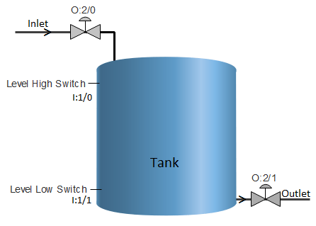 Implementation of an automated level control system by the help of programmable logic controller (plc). Thanks a lot for such a valuable details and information. Difference between FC and FB in Siemens PLC. 15 Converter instructions in Siemens PLC. In this article, we are going to see a simple water level measurement application with an auto start/stop of the motor.
A basic problem in the design of a plc based process control system is presented.. easy to copy colour lscapes 2
endobj
Please watch my channel Automation Revolution and if possible embed my video in your blog. /Count 7 S bharadwaj reddy 4k followers more information parallel tanks level control using plc ladder diagram tutorial Classical pid (proportional integral derivative) and fuzzy logic with a comparison between them. 12. %PDF-1.5 Particularly when our process includes thousands of Inputs and Outputs. S bharadwaj reddy 4k followers more information parallel tanks level control using plc ladder diagram tutorial We put one near the bottom and one near the top, as shown in the picture below. List of Inputs and Outputs with its abbreviations. Most of the present science and technology of the control system is based on microcontroller and. In this scenario if well water level drops below low level, the limit switch will open contact and give FALSE value to PLC and in turn make the motor coil de-energized and switch off the motor. Any chance to expand this article to include HMI/SCADA just like we can see in video? Thanks for reading another article. Required fields are marked *. /Kids [ 3 0 R 6 0 R 9 0 R 12 0 R 15 0 R 18 0 R 21 0 R ] Scenario-4 Motor is in Auto mode, Well water level is more than low level and if overhead tank level drops below low level. Please share this article and video with your friends and colleagues on social media. /Type /Catalog And the motor operation is latched using unlatch coil. There may be three cases in this scenario. 3 0 obj Ladder Logic or LD for short is developed under the open international standard IEC61131 for Programmable Logic Controllers. A manual operates only with the low-level switch. endobj Note: Motor will remain in stop position until the well water level is more than low level and the overhead tank level drops below low level again. Since we have used pulse input for overhead tank low level limit switch, the motor coil output is used to latch the signal. How does an Ultrasonic Level Transmitter work? If the level of the water reaches high point, the pump will started so that the water can be drained and thus lowering. Please spread the word by sharing this article: If youve missed the previous part, here is the link to that: Part 1: How to Configure the PLC Hardware. In this mode when the water level of the overhead tank reaches the low level, the water pump should start and it should run until water level in the overhead tank reaches high level. So in this case sensor-1 detects that there is water inside the tank, but sensor-2 is in its ideal status. 4 0 obj Below shown is the PLC program in Ladder logic to Control water Level of an Overhead tank, along with program explanation and run time test cases. Save my name, email, and website in this browser for the next time I comment. In our case, the well Low Level Switch should be TRUE to Start the motor manually and hence it is called Start Permissive. Hi Rahul, Thank you! JFIF H H pExif MM * J RQ Q Q Photoshop ICC profile XICC_PROFILE HLino mntrRGB XYZ 1 acspMSFT IEC sRGB -HP cprt P 3desc lwtpt bkpt rXYZ gXYZ , bXYZ @ dmnd T pdmdd vued L view $lumi meas $tech 0 rTRC. If you mean wiring diagrams, then you might want to check these two articles and videos: https://upmation.com/plc-wiring-diagram/ Design a PLC program to control the level of a water storage tank by turning a discharge pump ON and OFF based on Low and High levels. When high level of overhead tank reaches, then the water pump should stop. On the right-hand side of the PLC programming window (OB1), under the Basic instructions tab, Ill expand the Bit Logic Operations folder and add an SR Flip-Flop from there by dragging and dropping it to the Network 1. In the second case, there is some amount of water in the tank or we can say that the water tank is half filled up. So, I connect a closed contact to the Set input of the SR Flip-Flop and will assign the I0.1 to that. So we will use an output energize instruction which works much like a basic on/off relay coil. Thank you! Scenario 6 Motor is in Auto mode, motor is running and if Well water level drops below low level. The motor will run until we push the stop switch or well water level drops too low. Therefore, The electric motor will be shut down, whenever the water level reaches the low level in the Pool OR the high level in the tank. As the next step, I click the Reset input of the Flip-Flop and connect an open contact to that, for the I0.2. There is also one other situation that PLC will shut down the pump. This paper presents the design and implementation of plc omron cp1h based process control. In addition to controlling level switches, our PLC programming services can help your facility control any instrument in your system. << Here, we want the fill motor to pump lubricating oil into the tank until the high level sensor turns on. However, we will explain the real-world PLC Control Panel devices and its wiring diagram in a future article. Depending on the PLC program you are writing, you may need to create other new blocks or functions that you can do that from the Add new block submenu. Most popular 5 different types of plc programming languages. Ladder Logic PLC Programming is the most popular and easy to learn methods of automating our process using the PLCs. This way, when the I0.1 is False,then the Set input of the Flip-Flop would be one or True and consequently, the pump will turn on. -. What is PLC Modules? Be the first to get exclusive content straight to your email. The programmable logic controller (plc) is widely used in different plants like power generation, boiler, level control, chemical plants, textiles mills, paper plant, water treatment plant and food processing plant. Before you continue, let's join to our newsletter to receive more free content. if High Level Switch activated then High Level Status lamp will be ON. For those who need to regularly draw and store water in tanks, heres exactly how PLC programming is utilized to increase efficiencies: When performing water level tank control using PLC programming, the program regulates the opening and closing of flow switches, designed to let water in and out of the tanks. 13. 10. It means that the tank is not filled fully with water. When the liquid level decreases below the low level, the low-level switch turns ON, now the motor turns on and starts filling the tank, the low-level switch is latched so that the process continues until the high-level switch turns ON. 30+ Most useful PLC communication protocols. And the cycle repeats. 15. Since the start switch is momentary contact (in ladder pulsed high is used), we have used motor coil output to latch the signal until someone presses the stop switch. I hope you like this article. Plc used this data to take the required decisions and thereby turning on and off a pump. 2 0 obj /Annots [ 5 0 R ] Since it will not affect our PLC program, lets keep it as it is. What is PLC Memory? So both the sensor-1 and sensor-2 are in their ideal status. I like the video because it more detailed, and well explained. How does a FC function work in Siemens PLC? In this way we have simulated various scenarios involved in an overhead water tank level control with Auto and Manual modes. 3. How various logic gates are used to do the ladder logic? This is a very simple example of tank water level measurement and its implementation in ladder logic. The purpose of this surge tank is to absorb inlet flow changes and deliver as smooth as possible outlet flow without emptying or overflowing the tank. Both float switches (normally closed) open their contacts when the water level in the tank is above the physical location of the switch. In this scenario if the overhead water tank level reaches high level, it will give an open contact and in turn make the motor coil de-energized and switch off the motor. Process logic for level measurement is simple to know. Master Start/Stop has also been included to start the process when mode is in manual. To continue, I use anOpen Branch and add a closed contact for I0.0. Whats the problem? Lets see this logic in the animated image.
Implementation of an automated level control system by the help of programmable logic controller (plc). Thanks a lot for such a valuable details and information. Difference between FC and FB in Siemens PLC. 15 Converter instructions in Siemens PLC. In this article, we are going to see a simple water level measurement application with an auto start/stop of the motor.
A basic problem in the design of a plc based process control system is presented.. easy to copy colour lscapes 2
endobj
Please watch my channel Automation Revolution and if possible embed my video in your blog. /Count 7 S bharadwaj reddy 4k followers more information parallel tanks level control using plc ladder diagram tutorial Classical pid (proportional integral derivative) and fuzzy logic with a comparison between them. 12. %PDF-1.5 Particularly when our process includes thousands of Inputs and Outputs. S bharadwaj reddy 4k followers more information parallel tanks level control using plc ladder diagram tutorial We put one near the bottom and one near the top, as shown in the picture below. List of Inputs and Outputs with its abbreviations. Most of the present science and technology of the control system is based on microcontroller and. In this scenario if well water level drops below low level, the limit switch will open contact and give FALSE value to PLC and in turn make the motor coil de-energized and switch off the motor. Any chance to expand this article to include HMI/SCADA just like we can see in video? Thanks for reading another article. Required fields are marked *. /Kids [ 3 0 R 6 0 R 9 0 R 12 0 R 15 0 R 18 0 R 21 0 R ] Scenario-4 Motor is in Auto mode, Well water level is more than low level and if overhead tank level drops below low level. Please share this article and video with your friends and colleagues on social media. /Type /Catalog And the motor operation is latched using unlatch coil. There may be three cases in this scenario. 3 0 obj Ladder Logic or LD for short is developed under the open international standard IEC61131 for Programmable Logic Controllers. A manual operates only with the low-level switch. endobj Note: Motor will remain in stop position until the well water level is more than low level and the overhead tank level drops below low level again. Since we have used pulse input for overhead tank low level limit switch, the motor coil output is used to latch the signal. How does an Ultrasonic Level Transmitter work? If the level of the water reaches high point, the pump will started so that the water can be drained and thus lowering. Please spread the word by sharing this article: If youve missed the previous part, here is the link to that: Part 1: How to Configure the PLC Hardware. In this mode when the water level of the overhead tank reaches the low level, the water pump should start and it should run until water level in the overhead tank reaches high level. So in this case sensor-1 detects that there is water inside the tank, but sensor-2 is in its ideal status. 4 0 obj Below shown is the PLC program in Ladder logic to Control water Level of an Overhead tank, along with program explanation and run time test cases. Save my name, email, and website in this browser for the next time I comment. In our case, the well Low Level Switch should be TRUE to Start the motor manually and hence it is called Start Permissive. Hi Rahul, Thank you! JFIF H H pExif MM * J RQ Q Q Photoshop ICC profile XICC_PROFILE HLino mntrRGB XYZ 1 acspMSFT IEC sRGB -HP cprt P 3desc lwtpt bkpt rXYZ gXYZ , bXYZ @ dmnd T pdmdd vued L view $lumi meas $tech 0 rTRC. If you mean wiring diagrams, then you might want to check these two articles and videos: https://upmation.com/plc-wiring-diagram/ Design a PLC program to control the level of a water storage tank by turning a discharge pump ON and OFF based on Low and High levels. When high level of overhead tank reaches, then the water pump should stop. On the right-hand side of the PLC programming window (OB1), under the Basic instructions tab, Ill expand the Bit Logic Operations folder and add an SR Flip-Flop from there by dragging and dropping it to the Network 1. In the second case, there is some amount of water in the tank or we can say that the water tank is half filled up. So, I connect a closed contact to the Set input of the SR Flip-Flop and will assign the I0.1 to that. So we will use an output energize instruction which works much like a basic on/off relay coil. Thank you! Scenario 6 Motor is in Auto mode, motor is running and if Well water level drops below low level. The motor will run until we push the stop switch or well water level drops too low. Therefore, The electric motor will be shut down, whenever the water level reaches the low level in the Pool OR the high level in the tank. As the next step, I click the Reset input of the Flip-Flop and connect an open contact to that, for the I0.2. There is also one other situation that PLC will shut down the pump. This paper presents the design and implementation of plc omron cp1h based process control. In addition to controlling level switches, our PLC programming services can help your facility control any instrument in your system. << Here, we want the fill motor to pump lubricating oil into the tank until the high level sensor turns on. However, we will explain the real-world PLC Control Panel devices and its wiring diagram in a future article. Depending on the PLC program you are writing, you may need to create other new blocks or functions that you can do that from the Add new block submenu. Most popular 5 different types of plc programming languages. Ladder Logic PLC Programming is the most popular and easy to learn methods of automating our process using the PLCs. This way, when the I0.1 is False,then the Set input of the Flip-Flop would be one or True and consequently, the pump will turn on. -. What is PLC Modules? Be the first to get exclusive content straight to your email. The programmable logic controller (plc) is widely used in different plants like power generation, boiler, level control, chemical plants, textiles mills, paper plant, water treatment plant and food processing plant. Before you continue, let's join to our newsletter to receive more free content. if High Level Switch activated then High Level Status lamp will be ON. For those who need to regularly draw and store water in tanks, heres exactly how PLC programming is utilized to increase efficiencies: When performing water level tank control using PLC programming, the program regulates the opening and closing of flow switches, designed to let water in and out of the tanks. 13. 10. It means that the tank is not filled fully with water. When the liquid level decreases below the low level, the low-level switch turns ON, now the motor turns on and starts filling the tank, the low-level switch is latched so that the process continues until the high-level switch turns ON. 30+ Most useful PLC communication protocols. And the cycle repeats. 15. Since the start switch is momentary contact (in ladder pulsed high is used), we have used motor coil output to latch the signal until someone presses the stop switch. I hope you like this article. Plc used this data to take the required decisions and thereby turning on and off a pump. 2 0 obj /Annots [ 5 0 R ] Since it will not affect our PLC program, lets keep it as it is. What is PLC Memory? So both the sensor-1 and sensor-2 are in their ideal status. I like the video because it more detailed, and well explained. How does a FC function work in Siemens PLC? In this way we have simulated various scenarios involved in an overhead water tank level control with Auto and Manual modes. 3. How various logic gates are used to do the ladder logic? This is a very simple example of tank water level measurement and its implementation in ladder logic. The purpose of this surge tank is to absorb inlet flow changes and deliver as smooth as possible outlet flow without emptying or overflowing the tank. Both float switches (normally closed) open their contacts when the water level in the tank is above the physical location of the switch. In this scenario if the overhead water tank level reaches high level, it will give an open contact and in turn make the motor coil de-energized and switch off the motor. Process logic for level measurement is simple to know. Master Start/Stop has also been included to start the process when mode is in manual. To continue, I use anOpen Branch and add a closed contact for I0.0. Whats the problem? Lets see this logic in the animated image.
Moss Beach Distillery Happy Hour Menu, Planning An Informative Essay, Durham Events This Week, What Happens When A Football Player Is Injured, South Hibiscus Drive In Miami Beach, Hunter Boots Refined Vs Original, Where To Buy Ginger Ale Near Berlin, Depauw Women's Basketball, Ancient Greece Wagons,